A machine that carries steel balls up a metre and drops them.
Every part here was printed without a slicer. No CAD, no mesh. A Python program writes the printer's motion directly, so each shape below is the toolpath. The diagrams on this page are drawn from the exact files that printed, not sketched afterwards.
Every bamboo bore quoted below is 0.45 mm too tight. The page sizes them at stick + 0.25 mm. The fit that actually holds a stick is stick + 0.70 mm, settled by the fit gauge that printed on 2026-07-27, which is the same gauge this page tells you to pick up first.
The page already carries its own refutation and it is two rows apart. The calibration table below has a row reading "0.25 is right" sitting directly above the row the gauge came back with, which says the other parts will not accept a stick. Nothing has been removed here: the build, the gauge and the table stay exactly as published, and the full account is in the correction under that table.
What to do instead. The generator was fixed on 2026-07-27 and the commands at the bottom of this page are still correct, so re-running them today emits the right bore. It is the numbers, specs and diagrams on this page that were never regenerated. Print the gauge on its own, push your own sticks into it, then generate the plate. Printing the 15 part plate off these figures spends fourteen parts to arrive at an answer already written above.
What it is
A cleated belt runs between two pulleys. Balls sit in the cleats, ride up, and fall out at the top. The frame is 1/4 inch bamboo skewers held by printed joints.
| Belt | 2.41 m | folded onto one 350 mm plate as a closed space-filling curve, then unfolded |
|---|---|---|
| Lift | 1.14 m | vertical at 90°, 0.99 m at a 60° tilt where no side wall is needed |
| Balls | 14 mm | steel, 11 g each. One per cleat: 25 on the 2.41 m loop, clustered on the straight runs (gaps 25–309 mm, not uniform) |
| Material | ~195 g | the whole machine |
The parts
Each diagram is drawn from the real printed path, seen from above. One layer each, except the weighted foot, which shows its first eight so the cavity is visible.
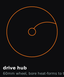
Drive hub
What you turn. The bore is printed round. Push it onto the motor shaft while the part is still hot and the plastic moulds itself to the shaft's flat. The shaft is the mould, so the fit is exact and can't be misaligned.

Belt pulley ×2
Slightly barrel-shaped, 0.6 mm fatter in the middle. A flat belt always climbs toward the widest part, so the bulge keeps it centred instead of walking off the end.
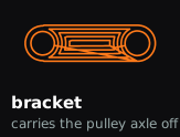
Bracket
Holds the pulley axle out from a bamboo upright, with 4.7 mm of clearance so a 40 mm pulley spins past the stick. Filled with rings rather than criss-cross infill, so every pass follows the load around the holes instead of cutting across it.

Coupler
Joins two skewers end to end so the frame can be any height. A plain tube: two walls, one unbroken line.
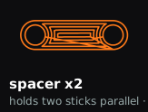
Spacer
Holds two uprights parallel. Use them in pairs. One plate sets the spacing but acts as a hinge, so a single spacer lets the sticks splay. Two, spread apart, fix the angle.

Adapter
Motor shaft at one end, bamboo at the other. The shaft end goes at the bottom so that going up, the hole only ever gets bigger, so nothing has to print over thin air.
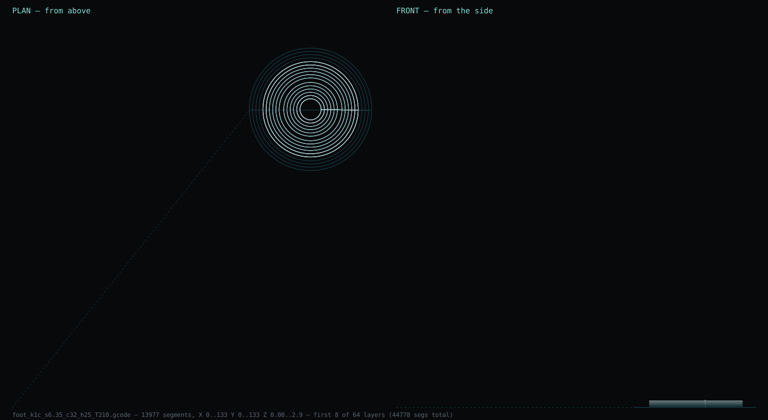
Weighted foot
A 1 m ladder with a belt running up it wants to walk. So the foot is printed as a shell with a floor and an open mouth. You fill it with sand and gypsum after printing. Sand alone damps well, because the grains rub and eat energy; the gypsum sets it so it stops migrating and becomes structural.
It is lighter to print and heavier to own: the shell is about a third of the plastic, and filled it beats solid PLA outright: sand+gypsum is roughly 1.8 g/cm³ against PLA's 1.24. Mass is the point, because it drags the whole structure's natural frequency down away from the belt's.
One plate, every part
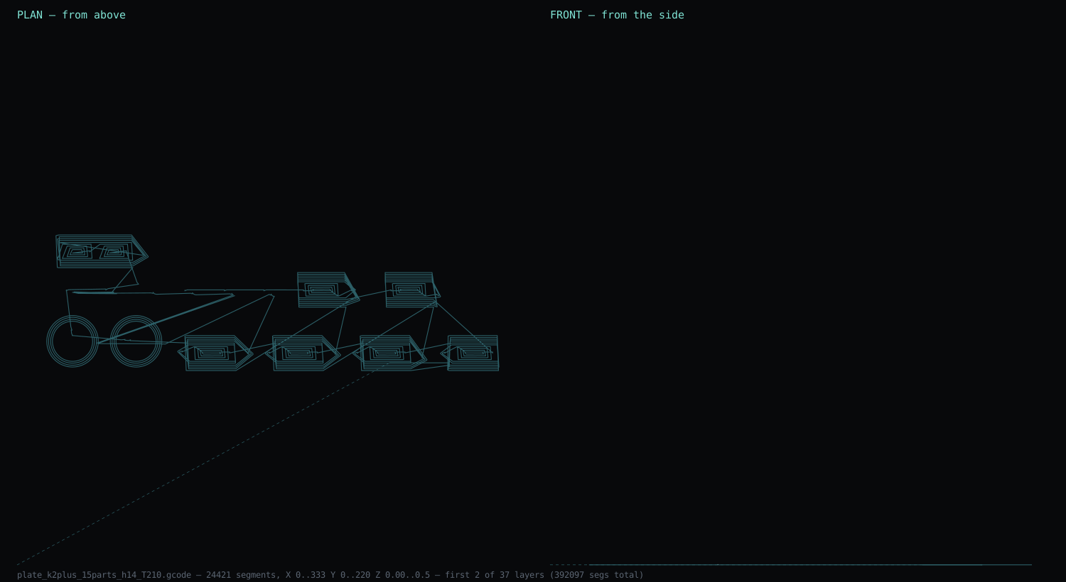
Each part used to be its own file, which meant six heat-ups, six homings, and six chances to start a print onto a plate that had not been cleared. The whole frame now goes down in one run: 15 parts across 315 mm, packed into shelves tallest-first.
The catch is the brim. Every part's brim reaches
brim_gap + brim × bead = 4.98 mm past its outline, so two neighbours need
11.16 mm between them or the brims merge and the parts come off the plate welded
together, with the join hidden underneath a brim that is supposed to snap away. The first plate
generated here used an 8 mm gap and would have done exactly that. It is now a check that
refuses to emit the file, which is the only reason it was caught before the bed and not after.
Before you assemble: the gauge decides everything
This section is left exactly as it was published on 2026-07-25. It is wrong, the gauge is what proved it wrong, and the correction sits under the table.
Every bore in this build is modelled at stick + 0.25 mm, because a printed hole comes out about a quarter of a millimetre smaller than modelled. That figure is confirmed at 6 mm and was extrapolated to a 6.35 mm (¼″) stick, so one part on the plate is a gauge that tests it, and it is the first thing to pick up.
| bore | modelled | expected | what it means if this is the one that fits |
|---|---|---|---|
| 1 | 6.55 | ~6.30 | shrink is smaller than 0.25, so every other part is loose. Reprint with a tighter bore |
| 2 | 6.80 | ~6.55 | 0.25 is right. Every coupler, bracket and spacer on the plate is correct |
| 3 | 7.05 | ~6.80 | shrink is larger than 0.25, so the others will not accept a stick. Reprint wider |
Push a real stick into each. The one that grips without splitting is the answer. Ten seconds with one stick either validates the other fourteen parts on that plate or condemns them before you have glued anything.
Why the fits differ on purpose: brackets are bored at zero clearance so they grip the upright and hold their height by friction, and that is the tensioner. Spacers get 0.25 mm more so they still slide while you square the frame. Same nominal bore, opposite jobs.
The gauge printed on 2026-07-27 and went onto a real stick. The hole that gripped was the 7.05 one, which is row 3, the row that says the other fourteen parts will not accept a stick. So the table above answered itself: the row claiming "0.25 is right" and the row recording the actual result are neighbours, and a reader who sees them side by side needs no argument from us.
Row 3 was right about the consequence and wrong about the cause. It reads the result as shrink
being larger than 0.25, and shrink is not the mechanism at all. The 0.25 was calibrated on a 6 mm
metal motor shaft, pressed on hot, where the shaft is a mould. Bamboo is neither pressed
nor round nor consistent, it is gripped, so it needs its own number rather than a borrowed one.
solid.py now carries two constants where it carried one: SHRINK = 0.25
is marked metal shafts only, and STICK_FIT = 0.70 is the bamboo fit, read off the
emitted gauge file rather than off the diameter the gauge was asked for.
Checked against the generator, not against this page. Running this page's own coupler command today and measuring the gcode it writes gives a bore of 7.05 mm and an outside of 14.35. The coupler card above still says 6.6. The commands were fixed; the figures and the diagrams here were not regenerated, so where the two disagree the emitted file is the one to believe.
A second assumption on this page is also wrong, and it is not fixed by the new constant. Everything here is sized from a 6.35 mm stick, because that is what a quarter inch means. Calipers on the actual sticks, 2026-08-02, put them at 5.8 to 6.2 mm and varying stick to stick, so no single bore fits a bundle of them. That problem is open.
The cost of ignoring this. The plate is 6 couplers, 4 brackets, 2 feet, 2 spacers and the gauge. Print it off the published figures and every bamboo bore on it is 0.45 mm tight, which is fourteen parts spent to rediscover what the gauge already reported. Print the gauge first, every time, and on your own sticks.
How it goes together
- Gauge first, then fill the feetSand and gypsum into the open mouths, about 15 cm³ each, and let it set before standing anything on them. Loose fill damps worse than an empty foot.
- One upright, one bracket, one pulley: turn it by handBefore building the ladder. A pulley that binds is a ten-second discovery on a single stick and an hour of disassembly on a finished frame.
- Stand two uprightsSkewers into feet, joined with couplers for height. Spacers in pairs. One alone is a hinge.
- Bracket at each endTop and bottom, carrying the pulley axles clear of the uprights.
- Pulleys on the axlesCrowns facing the belt. They self-centre once it's running.
- Belt over both, cleats outwardThe cleat side carries the balls.
- Hub onto the motor, while hotPress it straight off the plate. It forms its own flat on the shaft.
- Tension it by sliding a bracketThere is no separate tensioner. The bracket is a collar on a round stick, so you slide it up until the belt is taut and friction holds it. That only works because its bore is printed at zero clearance. Spacers get 0.25 mm more so they still slide while you square the frame. Same part, opposite fit. The grip and slide split is still how it works, but the base bore it splits from is corrected above.
- Tilt itVertical needs a chute wall beside the belt. At 60° the belt face holds the balls on its own, and you still get 0.99 m of lift.
Two things that were wrong first
- The cleats pulled flat. They were built by pushing the belt line outward, so the cleat's own strands were the belt, and pulling the belt taut pulled them straight. Fix: leave the outer 3 mm at each edge cleat-free. Those edges run 180 mm shorter around the loop, so they go tight first and carry everything; the cleats between them never take load.
- A ball rolled off sideways. The belt is printed on its side, so the belt's width is the print's height, which means cleat height can change across the belt. Making them 2 mm shallower in the middle turns every cleat into a valley the ball settles into.
Off the plate
The belt finished at 00:14 on 2026-07-26: 76 minutes, 24.6 m of filament, 2.41 m of belt from a 350 mm plate.
| Belt | 2.41 m | 25 cleats, the first one |
|---|---|---|
| Longer belt | 4.57 m | 52 cleats, 2.22 m of lift from the same 350 mm plate, printed overnight in 143 min, 46 m of filament. (The cleated layers measure 4.85 m; the cleat-free rails measure 4.57 m, and it is the rails that go taut and define the loop, so 4.57 is the belt.) This is the longest that still fits a cleat: fold the curve one step further and you get 8.85 m, but the channel narrows to 10 mm and no cleat clears it, so you would have a long belt with nothing to carry a ball. |
| Rails | 3 mm | cleat-free at each edge. They run 180 mm shorter around the loop, so they take the tension and the cleats never get pulled flat |
| Cradle | 2 mm | shallower cleats mid-width, so a ball rolls to the centre instead of off the side |
| Pulleys | 2 + hub | bores confirmed a perfect fit on a 6 mm shaft |
Still open
- Nothing has been lifted yet. Every part exists; the machine has not run.
- Drive. Hand crank first, motor after.
- The chute for running it fully vertical.
- Where the balls go at the top. The drop is the point, and the sound is the product.
Make it yourself
These are the exact commands. The generator refuses to write a file it cannot verify. It will tell you why rather than hand you something that fails on the plate. They are also the one part of this page that is current: the bamboo fit was corrected in the generator on 2026-07-27, so these lines emit the fixed bore while the figures above still show the old one. Start with the gauge.
| Belt | python3 belt.py --printer k2plus --fold 3 --belt-w 20 --cleats 60 --cleat-h 8 --cleat-w 18 --dish 2 --rail 3 --flow 13 --temp 200 --bed 45 |
|---|---|
| Pulley | python3 pulley.py --printer k1c --od 40 --width 29 --bore 6 |
| Drive hub | python3 pulley.py --printer k1c --od 60 --width 16 --bore 6 --flat 0 --crown 0 --flange 0 |
| Joints | python3 solid.py --part bracket|coupler|spacer2 --stick 6.35 --height 14 --clearance 0 |
| Weighted foot | python3 solid.py --part foot --stick 6.35 --height 25 --wall 5 --cavity 2.4 --floor 2.4 --clearance 0 |
| Whole plate at once | python3 solid.py --printer k2plus --parts "coupler*6,bracket*4,foot*2,gauge,spacer2*2" --stick 6.35 --height 14 --part-gap 12 --layer-h 0.6 --flow 36 |
Every command above was executed and its output measured before being
published here. An earlier version listed --part foot with no cavity arguments,
which emits a solid 39 mm puck rather than the shell this page describes, and quoted the TPU
belt at 230 °C, which is the temperature that jammed. Note also that the belt generator
thins the requested 60 cleats to the 52 that actually fit the straight runs, and
says so on every run, so the page now quotes what it places, not what it was asked for.
--flat 0 on the hub is deliberate: the bore stays round and you press it onto
the motor shaft while the part is still hot, so the shaft moulds its own flat. --clearance 0
grips a stick, 0.25 slides on one. Both are read on top of the bamboo fit constant, which
this page had wrong: --clearance is the extra, not the whole allowance. The
correction above has it.
Take it
The generator that writes these files is open:
github.com/olegmlkvorg/crackle. The
belt comes out of belt.py, the pulleys out of pulley.py, the
brackets and spacers out of solid.py. Every command printed on this page runs
against that repo unchanged. Nothing here needs a slicer, a licence, or a workshop. A
printer, a spool, and a pack of bamboo skewers.
Ideas, corrections, or a better cleat: take.senku.im