One day, 2026-08-06 · one part stood, unloaded · most of what follows is defects found
One day of the bucket, in nine photographs
The 320 by 300 mm bucket came off the printer that morning and stood, and that is the least instructive thing that happened. Nearly everything else photographed here is something being wrong in a traceable way: a base, twice; a first layer that had been wrong for a week inside a part that printed fine; a gate blind exactly where the design lived; a bore guessed twice and gauged twice, the second gauge built to be able to catch itself lying; one purge causing two different defects. How each was found is the useful half of the day, so that is what this page records.
One part printed and stood. The 320 by 300 mm bucket finished on 2026-08-06 after 8.09 hours and 249 g of filament. It has not been loaded, not weathered, not lived with. One part is one part.
A second, larger bucket was printing while the first eight sections were written. It did not survive its first four minutes: the base failed a third time and the run was cancelled. Section 9 is what the rest of that evening produced instead.
Several sections record a defect found and a cause located, not a fix proven. Where a correction has not yet been printed and measured, the text says so, and section 9 is the list of what this page cannot claim.
The part itself, with every figure drawn from its emitted gcode, is documented at bucket.senku.im. This page is the day. The photographs are unedited; each caption says what is in it; every number states whether it was measured off a file, read off a printed part, or guessed.
1 · The part, held
"It came out majestic, true pleasure to have it in my hands" Oleg, holding the finished 320 mm bucket, 2026-08-06
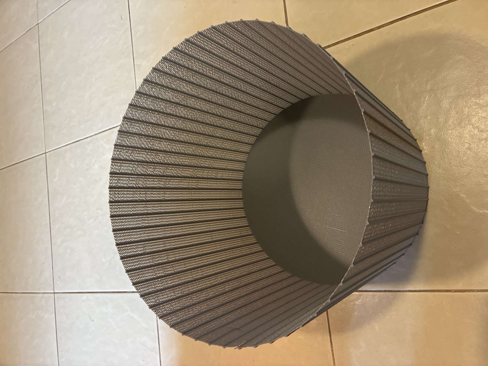
The wall is 56 vertical posts standing on a 320 mm circle, joined by horizontal bridges, with one thin strand crossing every gap on every layer. On paper that is an open cage. In the hand it is not, and the photograph shows why: between the post ribs there is a continuous woven membrane, not air.
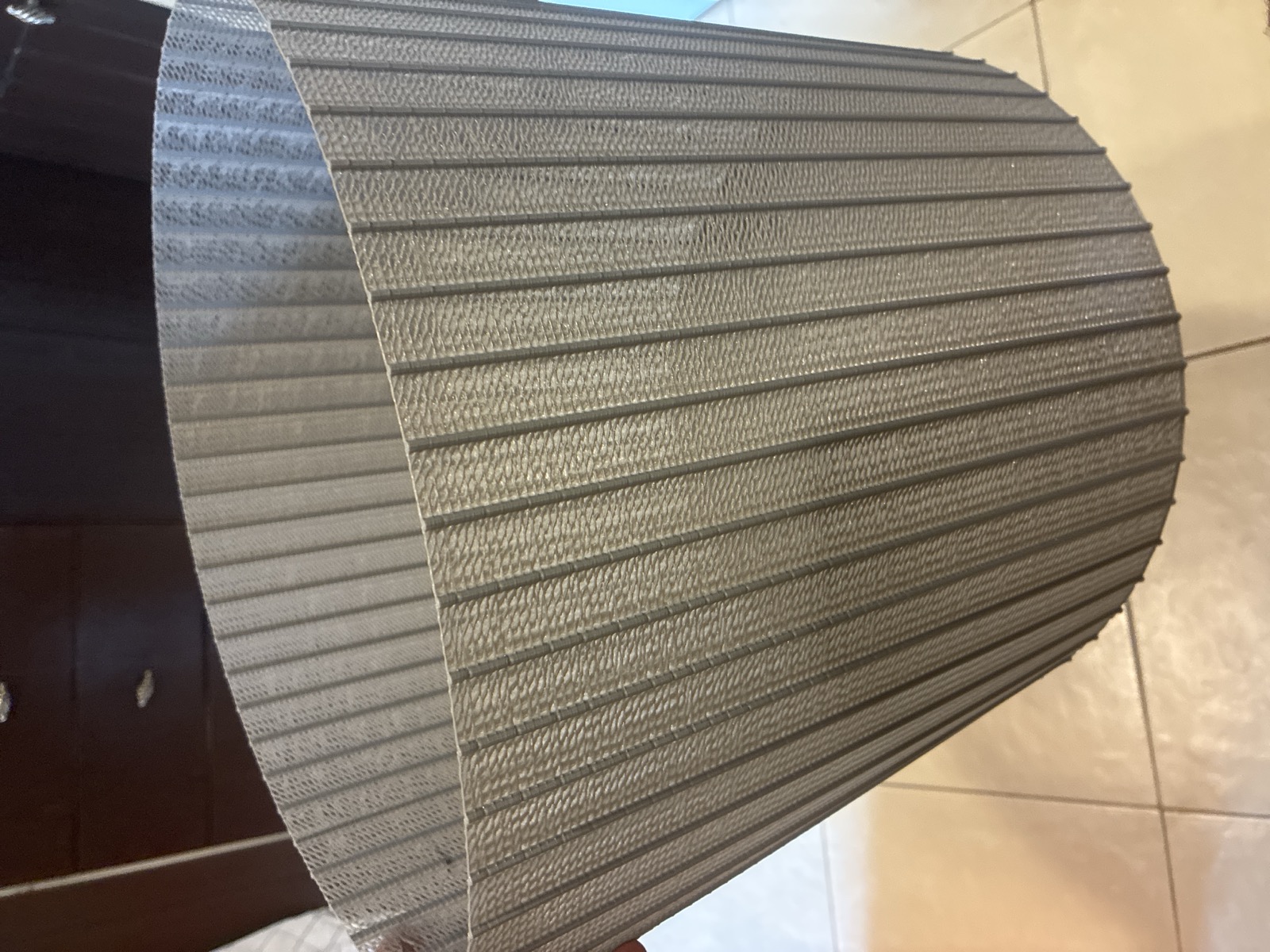
The membrane is measurable, and it was measured off the emitted gcode rather than designed in. The crossing bead is 0.0492 mm2/mm of path, an equivalent round diameter of 0.250 mm, laid at a 0.240 mm layer pitch. The ratio is 1.04: each strand lands touching the strand below it, so consecutive crossings fuse into a continuous sheet. 86 percent of the circumference is that sheet and 14 percent is post. The surprise is on the record because the file was measured after the part was held, not before.
2 · It saves neither material nor time
The obvious reason to build a wall from posts is to use less. Measured: 249 g against 307 g for an equivalent solid single-bead wall, only 19 percent less, because the crossings eat the saving. Nor does it save time: 6.72 hours of motion against 6.98. Both intuitions were wrong, and both numbers come off the emitted files rather than a model of them. Whatever this shape earns, it does not earn by thrift.
3 · The base failed twice, and one sentence explains both
"Base has not acceptable artifacts" Oleg, 2026-08-06, at the part in the next photograph
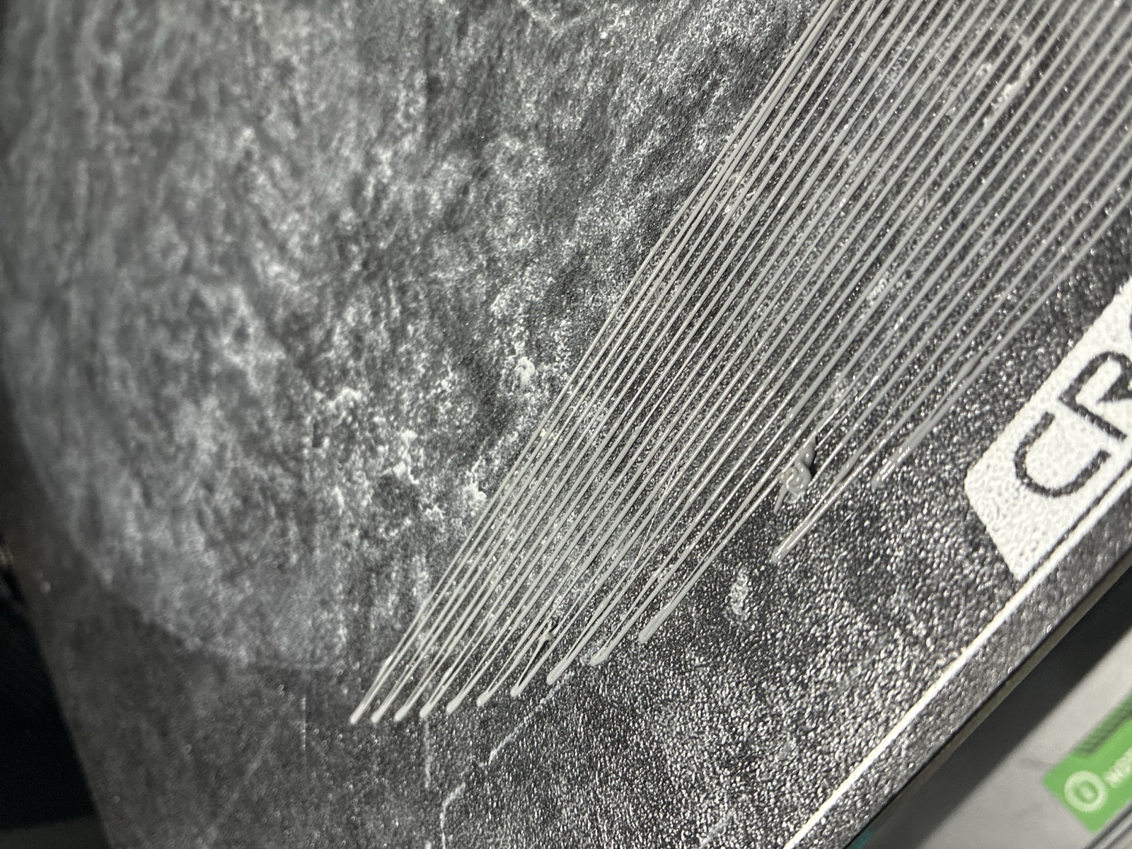
The sentence: press welds the layer, pitch spaces it. Oleg had asked for two things, less press and a non-solid base, and one knob was made to serve both. That opened the base by starving the weld, which is what the loose strands above are. The fix restores the proven press and opens the floor with pitch instead, so each request gets the knob that actually controls it.
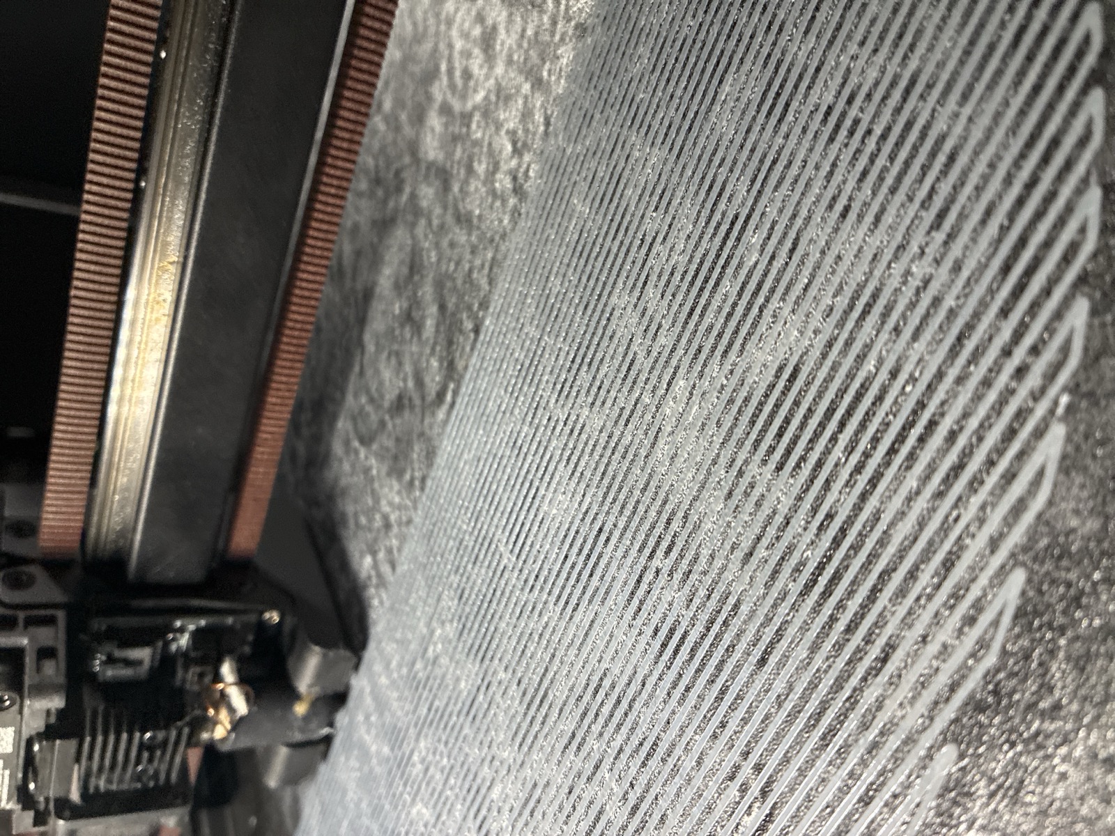
The fix has a boundary, and the gate found it: a floor opened to 3.2 mm pitch was refused by the overhang check at 20 percent unsupported, because five floor layers cannot stack on a lattice that open. The refusal is the system working, and it is on this page because a refusal that goes unrecorded reads later like a run that never happened.
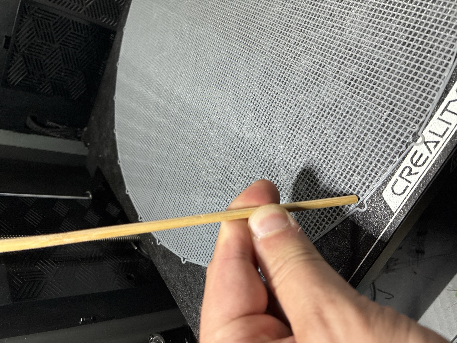
4 · A part that printed was never proof its first layer was right
A new first-layer gate, written during the five cancelled prints of the big bucket, failed an older bucket that had printed fine, and the failure was a true positive. That older file emits no Z offset, so on a machine whose zero sits 0.15 mm high it commanded 0.100 mm and landed at about 0.250. It printed anyway because its first layer ran 1.52 times flow, which welds a 1.20 mm bead straight through the error. The bigger bucket ran 1.02 times flow, landed a 0.80 mm bead, and took five cancelled prints before the offset was found. Same defect in both files. One was masked by excess, and the excess had been read as health.
When something works, ask why it worked. A print that succeeds for the wrong reason is a defect with good manners, and it will resurface in the first file that lacks the mask.
5 · The gate was blind exactly where the design lived
Three findings from reading the gate itself, after it had been trusted for days.
validate.py contained zero occurrences of
SET_GCODE_OFFSET, the value the whole first layer depends on. Its
overhang check reads move endpoints, so a bridge written as one move across 16 mm of open
air reported 0 percent unsupported. And a rule written after a base
detached requires Z on the move line, which this file format does not emit, so the rule
matched 0 moves here against 220,137 in the older design it was written
for.
A rule that matches nothing reports identically to a rule that found nothing wrong. Every one of these passes looked like the gate approving the design. The gate and the generators are public, in the crackle repository, so the blindness described here is checkable rather than confessed.
6 · The bore was guessed twice and measured once
A C-channel post must snap onto a 1/8 inch bamboo stick. Both guesses rested on a 0.25 mm shrink constant that had been calibrated on a 4 mm hole for a metal shaft and reused for bamboo, where the project's own notes already recorded it running 0.45 mm too tight and condemning about 21 parts. First guess: a modelled bore of 3.575 mm. Corrected guess: about 4.075. Then a gauge plate was printed, numbered cells at stepped bores, and real skewers were pushed into it. It said 4.550. Still 0.475 mm low after correcting once, which is almost exactly the 0.45 the notes had recorded and nobody re-read.
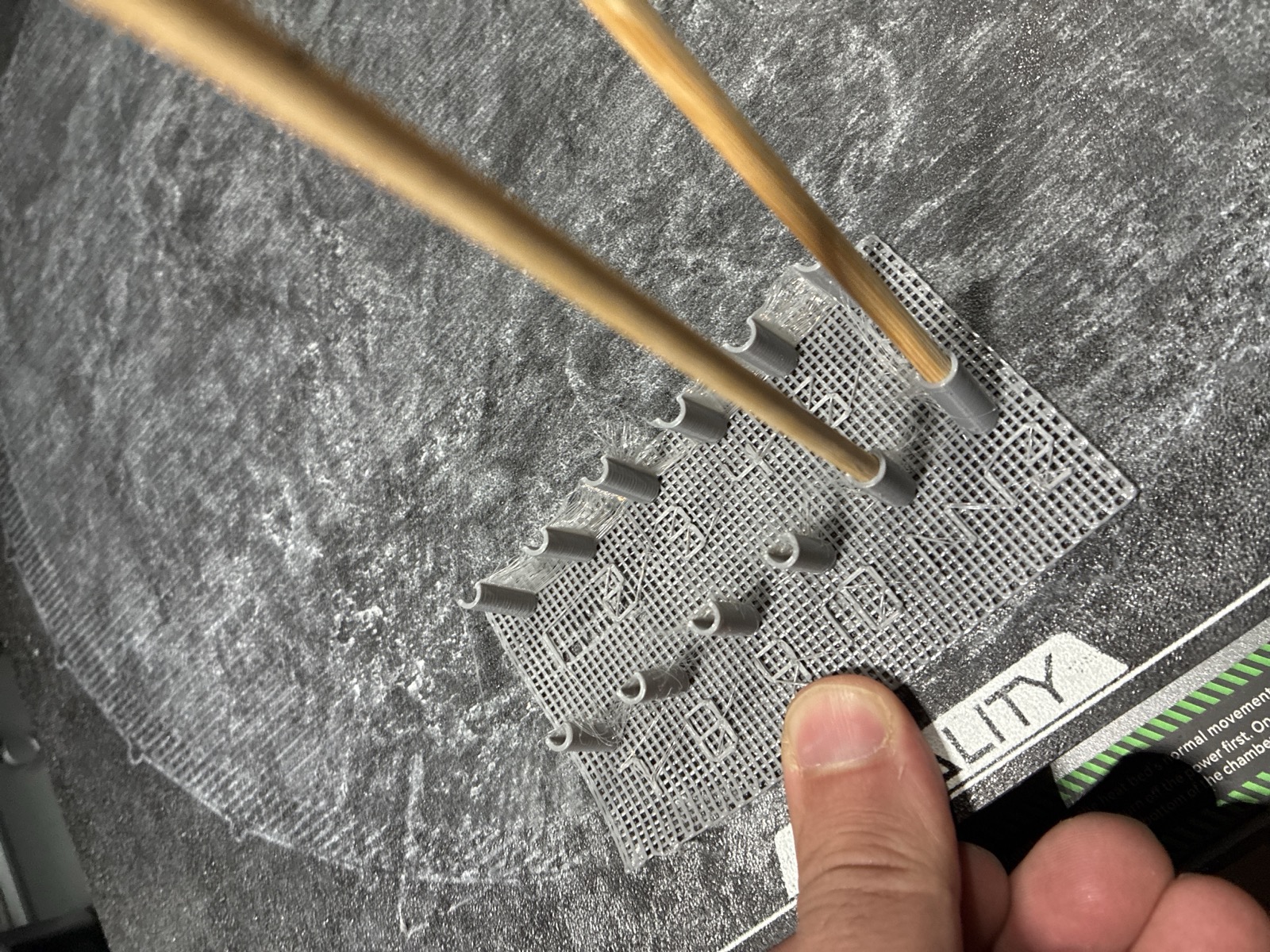
That reading stood for a few hours: one gauge, read once, no post printed at 4.550 and snapped onto a stick. It did not survive the evening. Section 9 is the second plate, the one built to be able to catch itself lying, and it moved the answer.
7 · One cause behind two artifacts
"The beginning of extrusion need to be improved generically" Oleg, 2026-08-06, at the nozzle in the next photograph
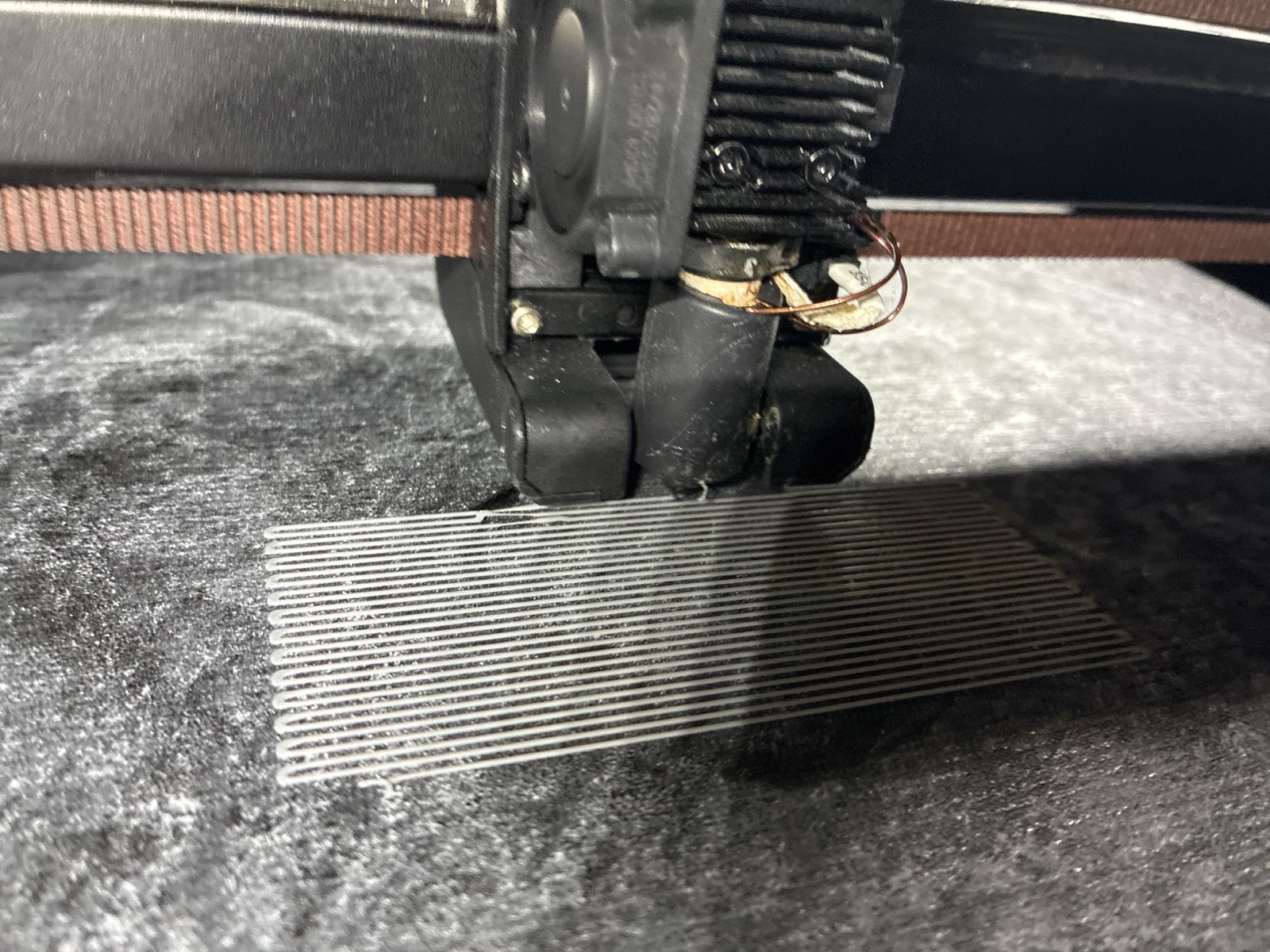
Every generator opened with 20 mm of filament purged into open air with the head stationary, a block copy-pasted into 31 files while the shared machine module carried no prime at all. Nothing pins a stationary extrudate, so it clumps on the tip, rides along, and eventually drops into the part. That is the blob above, and it is also the broken lines below: the purge that leaves with the nozzle is missing from the metering that follows it.
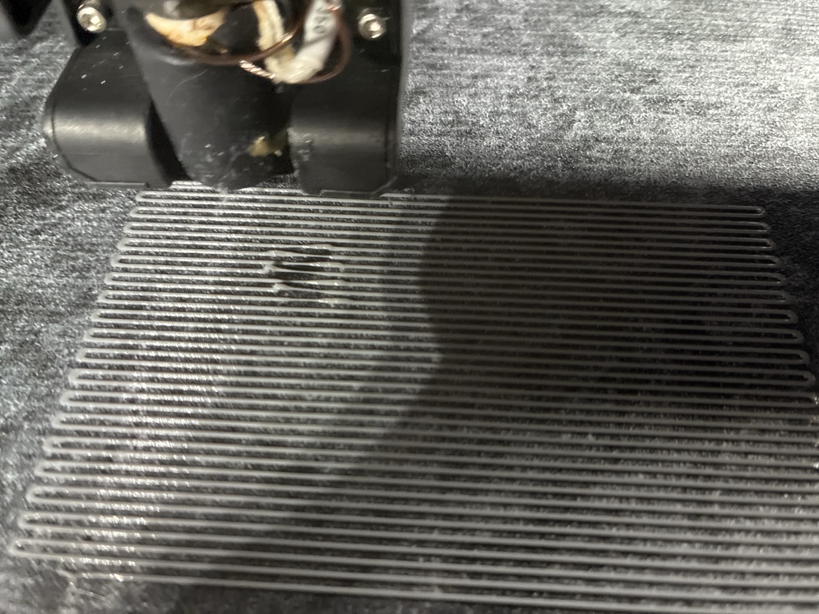
What ruled the generator out is the file's own metering: 0.2000 mm2/mm against a 0.2000 target, ratio 1.000, flat across every layer. A file that meters perfectly and prints broken points away from itself, toward the machine's start of extrusion. The cause is located. It is not yet removed: no redesigned prime has printed clean as of this page.
8 · The plate that should never have been printed
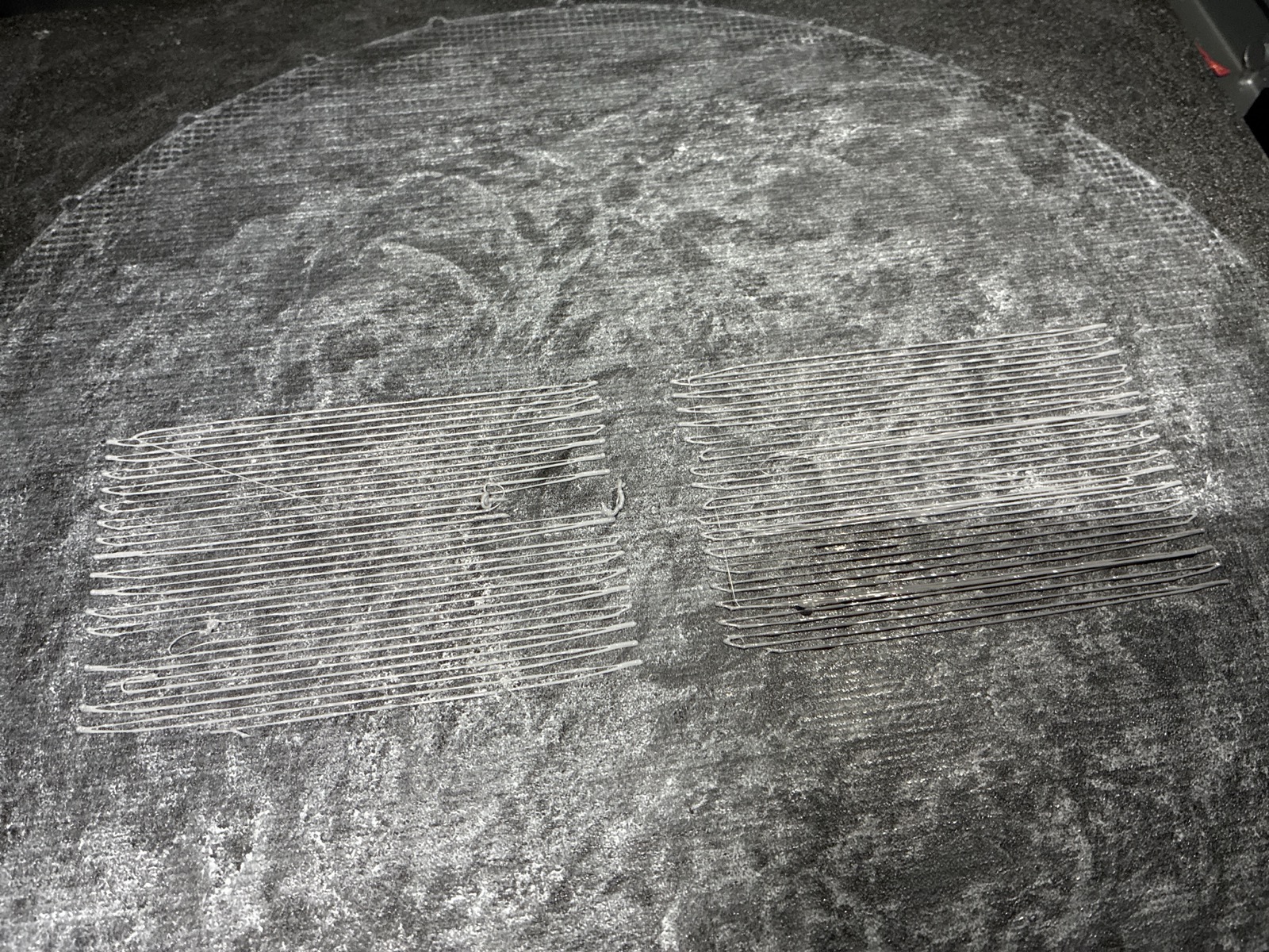
Two plates that day went to questions nobody had asked, and this one had already been predicted to fail. A prediction of failure is a reason not to print, not a caveat to attach afterwards. The gauge in section 6 is the same day's counter-example: one plate, one question somebody actually had, one number that ended two rounds of guessing. The difference between the two plates is not skill, it is whether anyone wanted the answer.
"Think what you doing before printing." Oleg, 2026-08-06. The day's standing correction, kept verbatim.
9 · The evening: a gauge built to call itself a liar
The larger bucket, its bore cut to the morning gauge's 4.550, went to the printer that evening for a nine hour run and was cancelled at four minutes: the base failed a third time. The response to a third failure was not a third guess at the bore. It was a plate that took 12.52 minutes of motion and was designed, before printing, to be able to prove itself wrong.
The plate is 12 numbered C-channel stubs, 18 mm tall, standing on one 100 by 60 mm base: six modelled bores from 3.60 to 4.60 mm across, two wrap angles, 250 and 280 degrees, down. Every cell's number is printed 0.72 mm proud of the base, so a photograph of the plate says which cell is which with nobody's memory involved. There is no photograph of this plate on the page yet; the figures below are traced from the emitted toolpath, the same file the printer ran.
First, what a C-channel is, because the whole experiment lives in one arc. It is a wall wrapped most of the way around a circle, leaving a slot, the mouth, where a stick is pressed in sideways. The wrap angle is how many degrees of the circle the wall covers, and it decides everything. Wrap far enough past the stick's widest point and the mouth is narrower than the stick: the lips must flex apart to admit it and close again behind it, which is a snap grip. Stop short of that and the mouth is wider than the stick, and nothing holds; there is nothing to click past. At these bores that line falls between 210 degrees, where the mouth is wider than the stick at every bore on this plate, and 250, where it is narrower for the smaller bores. That is why this plate runs 250 and 280 and why a gentler wrap was not worth printing.
Six bores by two wraps is the grid. The part of the plate worth publishing is the three cells that were expected to fail. Cells 4, 5 and 6 model a mouth wider than the stick, cell 4 by 0.117 mm, and the file's own header, written before anything printed, marks them as dropping straight through and instructs the reader to start there: if a cell marked drops-in grips the stick, the gauge is lying and nothing else on the plate can be read. A gauge with no cell that must fail cannot tell anyone when it is broken. This one could.
Oleg pushed a 1/8 inch bamboo stick into the cells and chose cell 4. The negative control held. That is not the experiment failing; it is the finding. A mouth modelled 0.117 mm wider than the stick gripped it anyway, so the printed wall sits tighter than the model says it should, which means the 0.25 mm shrink constant, the one already caught 0.45 mm wrong once before, understates the real shrink here too. The plate was built to be able to falsify that constant, and it did.
What that leaves, stated plainly:
- Known: on this printer, in this material, at this bead, a channel modelled at a 4.20 mm bore with a 250 degree wrap grips the stick the way the part needs. A toolpath is cut from modelled numbers, so this is the number a part can actually be cut to.
- Not known: the size of anything printed. Nobody has put calipers on a cell. The physical bore is smaller than the modelled 4.20 by the true shrink, and the true shrink remains unmeasured. One cell of one gauge is not a fit constant.
- Not settled: the morning gauge said 4.550 and this one says 4.20, a 0.35 mm disagreement. The morning plate printed starved, which is a reason to prefer the evening one, not a proof of it.
- No part has been printed at cell 4's numbers and snapped onto a stick. The number has not made anything yet.
The run itself, for the record: 12.52 minutes of motion; 1562.7 mm of filament consumed against 1550.66 emitted by the file; the Z offset read minus 0.150, the value the file sets, on all eleven samples taken during the print.
And the larger bucket is not waiting on the bore any more, which is not the same as being ready. Its bridges span 33.6 mm of open air, and the longest bridge any part on this page has actually held is 17.85 mm. Until a separate test says a strand can cross that gap, a part with the right bore and an unproven span is still a part that must not print.
10 · What this page cannot say
- Nothing about the larger bucket beyond its first four minutes. It was cancelled over its base, its bridges would have to cross nearly twice the span ever proven here, and no test of that span exists yet.
- Nothing about the standing bucket beyond that it printed and stood. It has not been loaded, carried anything, been left outdoors, or been measured against the file it came from.
- No strength number for anything photographed here.
- The bore figure is two gauges that disagree, 4.550 and 4.20, and the second is preferred for a stated reason, not proven. No cell of either plate has been measured with calipers, the shrink constant is still unmeasured, and no part has been printed at either number and snapped onto a stick.
- Section 9 records the one negative-control cell that was read against its prediction. What the other two predicted-loose cells did is not recorded here.
- The prime diagnosis names a mechanism consistent with both artifacts. The prime itself is unchanged until a fix prints clean, and no such print exists.
- The coupon plates' readings are only partly read, and the unread part may disagree with something above. If it does, the correction lands on this page next to what it corrects.